

This content is part of a larger document, the G1 Network Planning and Deployment Guide.
As mentioned in our previous blog, link quality is vital for a successful fixed wireless network. Link quality impacts overall throughput as well as reliability.
Metrics that are important to determine link quality include:
- Remote node (RN) alignment
- Pathloss and excess pathloss
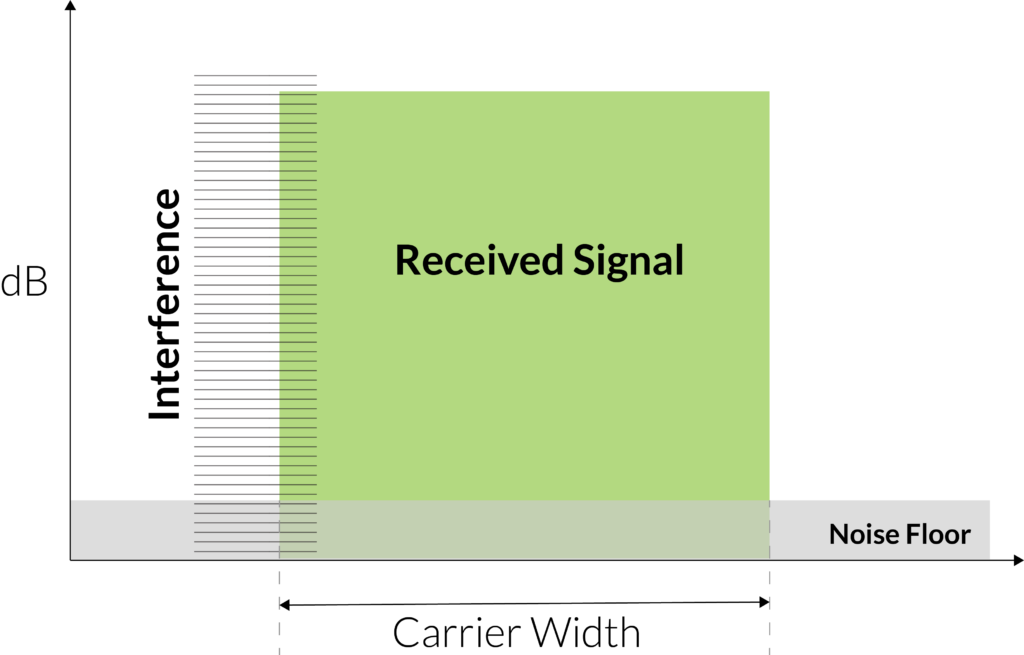
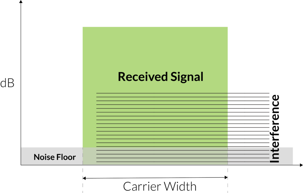
- Interference
- Signal-to-interference-and-noise-ratio (SINR)
- Sensitivity loss
- Received signal strength
Last time, we talked about the alignment of the RN and pathloss. This time, we’ll focus on the other metrics: interference, sensitivity loss, and received signal strength.
Alignment Metric
G1’s alignment metric is a unitless value between 0 and 30 that is available during RN installation. As the name suggests, this metric is used during the aiming portion of RN installation to ensure the best possible alignment with its serving base node (BN). Once an RN has completed calibration, you can adjust the tilt and azimuth to determine the highest alignment metric. As you adjust the tilt and azimuth, keep in mind that G1’s near-perfect multipath integration means G1 can use reflections and diffractions to get around obstacles that might otherwise prove troublesome. In some cases, the best alignment might not necessarily be with an RN pointing straight in the direction of the BN. It’s always worth taking a few minutes during installation to check out multiple orientations.
For a quick introduction to how G1 gets around obstacles, check out this blog or download the ngFWA Technology Primer.
While adjusting the azimuth of a radio is a logical installation step, adjusting tilt may be less so. Yet, the biggest change in performance can often result from tilt adjustment. This is because the RN has a 55° horizontal field of view and beamforms on the horizontal axis rather than the vertical. Most installations will use a 2–5° — although this can vary depending on the elevation difference between the RN and the BN in each case.
TCS reports several essential metrics that can be helpful in determining how much interference is impacting a link:
- Downlink and uplink SINR
- Sensitivity loss
- Received signal strength
Often, the level of interference an RN will hear in its vicinity differs significantly from what a BN hears on a tower. Each source of interference can impact link performance, albeit in different ways. For example, if an RN has a high INR (and therefore a lower SINR), it might have trouble receiving data from the BN. This could result in lower downlink performance. Conversely, if a BN is experiencing a high level of interference, it may have trouble receiving data from the RN, resulting in lower uplink performance. These are important distinctions that will make troubleshooting much easier if link degradation occurs.
Sensitivity Loss
Sensitivity loss is another helpful metric that indicates the peak received signal level on each carrier. This is system gain loss due to an increased noise figure. A non-zero value can indicate substantial interference. When considering the pathloss for a link, you should take the reported pathloss and add any sensitivity loss. For example, if a link has a pathloss of 125 dB and a sensitivity loss of 1 dB, the effective pathloss for that link is 126 dB.
Received Signal Strength
Received signal strength is the final metric of interest. This metric indicates the strength of the received signal on a given carrier regardless of whether it is the signal of interest or noise. If an RN is neither receiving transmissions from a BN nor experiencing external interference, the received signal strength should be close to the noise floor. If the RN is not receiving data and the receive signal is elevated from the noise floor, this can be an indication of interference in the view of the RN.
Summary
RN alignment, pathloss, interference, SINR, sensitivity loss, and received signal strength are all critical factors to consider when evaluating the performance of and troubleshooting a wireless link. Understanding the relationship between these metrics, as reported by TCS, will help operators build the best-performing networks and take full advantage of G1’s ngFWA capabilities.
If you just can’t wait to learn more, check out our other blogs or some of our favorite customer links. Or reach out to us at info@taranawireless.com. We’d love to hear from you.