

This content is part of a larger document, the G1 Network Planning and Deployment Guide.
Link quality is vital for a successful fixed wireless network. Without it, nothing else matters. To get a great link, there are many variables to consider. For those new to Tarana’s Gigabit 1 (G1) platform, we note that G1 has a number of metrics to help validate your links. These metrics are available through Tarana Cloud Suite (TCS) and the individual device web UI.
Metrics that are important to determine link quality include:
- Remote node (RN) alignment
- Pathloss and excess pathloss
- Interference
- Signal-to-interference-and-noise-ratio (SINR)
- Sensitivity loss
- Received signal strength
In this week’s blog, we’ll focus on the first two metrics and treat the others in a separate article.
Alignment Metric
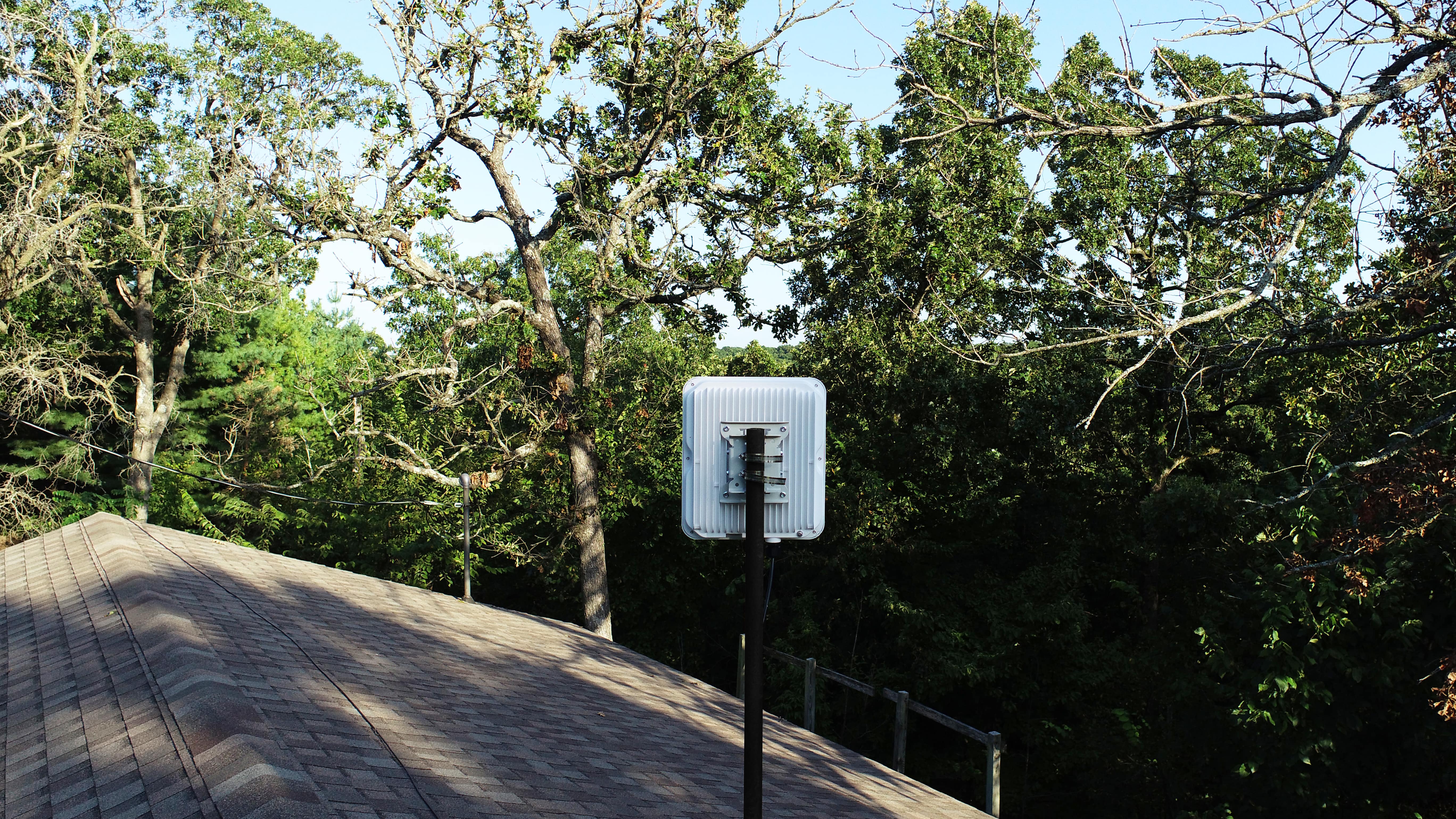
G1’s alignment metric is a unitless value between 0 and 30 that is available during RN installation. As the name suggests, this metric is used during the aiming portion of RN installation to ensure the best possible alignment with its serving base node (BN). Once an RN has completed calibration, you can adjust the tilt and azimuth to determine the highest alignment metric. As you adjust the tilt and azimuth, keep in mind that G1’s near-perfect multipath integration means G1 can use reflections and diffractions to get around obstacles that might otherwise prove troublesome. In some cases, the best alignment might not necessarily be with an RN pointing straight in the direction of the BN. It’s always worth taking a few minutes during installation to check out multiple orientations.
For a quick introduction to how G1 gets around obstacles, check out this blog or download the ngFWA Technology Primer.
While adjusting the azimuth of a radio is a logical installation step, adjusting tilt may be less so. Yet, the biggest change in performance can often result from tilt adjustment. This is because the RN has a 55° horizontal field of view and beamforms on the horizontal axis rather than the vertical. Most installations will use a 2–5° — although this can vary depending on the elevation difference between the RN and the BN in each case.
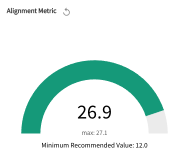
While an alignment metric of 12 is considered acceptable, we always recommend achieving a bit extra to account for changing conditions, such as additional trees or foliage impinging on the link.
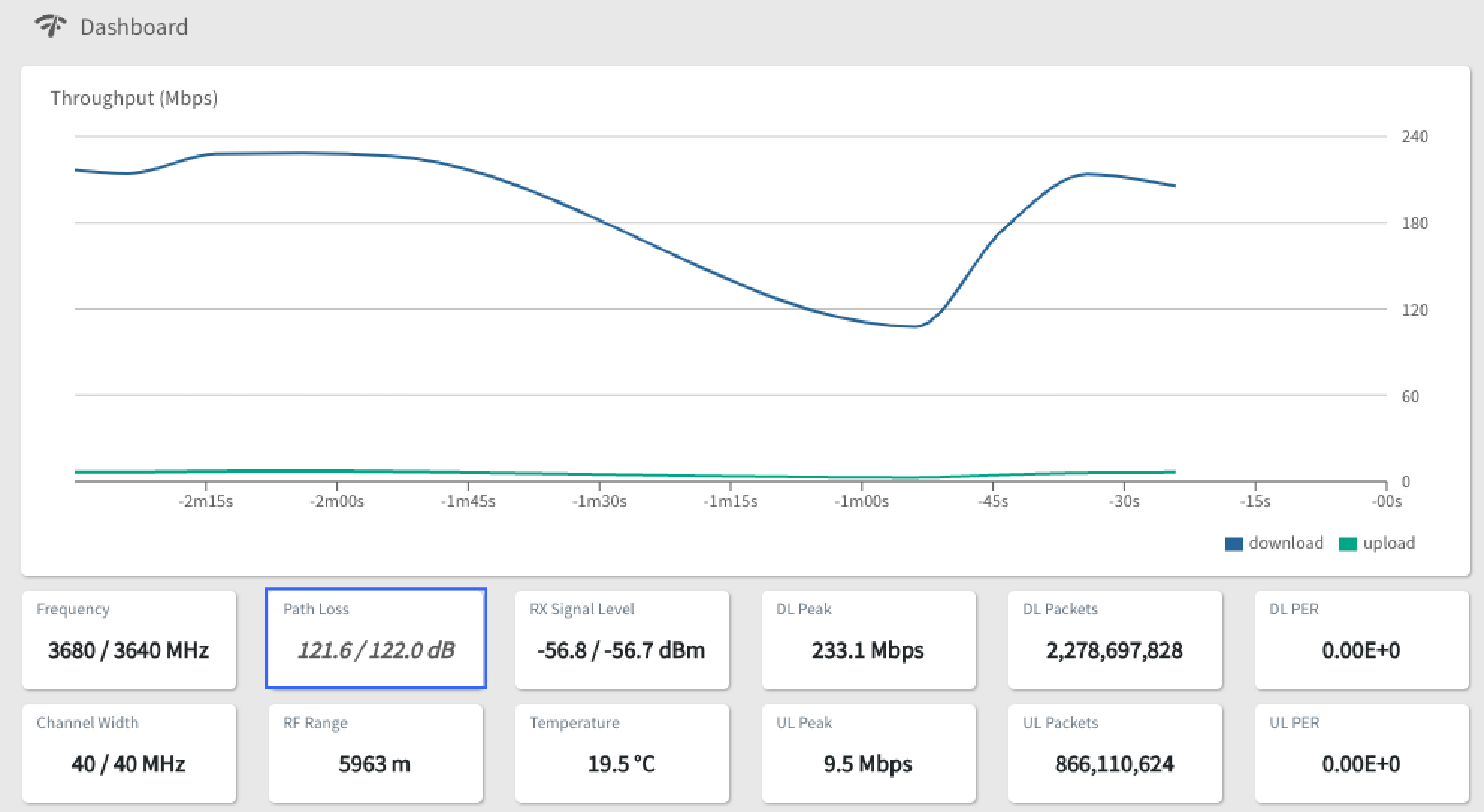
Pathloss and Excess Pathloss
Our second metric, pathloss, indicates how much signal attenuation occurs from one end of a link to the other. It’s a key indicator of expected performance and relates directly to achievable MCS level and throughput capacity. Ideal pathloss values vary depending on the radio frequency. For example, a pathloss of 130 dB can yield excellent results for a CBRS link, whereas a 5 GHz link needs closer to 120 dB for maximum capacity.
Excess pathloss refers to the amount of pathloss that occurs on a link over and above what is predicted via a free-space pathloss calculation. In general, the greater the excess pathloss, the more obstructed the link. An excess pathloss of 6 dB or less would be typical for a line-of-sight link, while a value of 20 dB or greater would indicate a non-line-of-sight link. Near-line-of-sight values will fall somewhere in between.
For improved troubleshooting, we recommend recording the pathloss and excess pathloss when a link is provisioned. This information can be stored on a per-link basis using the handy notes feature available on the RN’s single device page in TCS. This information can be useful when troubleshooting link performance at a later date.
Of course, the alignment metric and pathloss are not the only variables that determine overall link performance. In the next blog of this series, we’ll take a closer look at signal and interference strength.
If you just can’t wait to learn more, check out our other blogs or some of our favorite customer links. Or reach out to us at info@taranawireless.com. We’d love to hear from you.